Creating motorcycle fairing molds is not just about crafting plastic body panels; it’s a meticulous endeavor that merges design finesse with technical excellence. For business owners looking to enhance their product offerings or streamline their manufacturing processes, understanding how to make these molds is crucial. This guide unpacks the journey starting from the essential design phase through prototyping, leading into the intricate mold-making process. Each chapter is aimed at providing actionable insights and technical knowledge that can directly impact the production quality and efficiency.
From CAD to Cavity: Designing Motorcycle Fairing Molds That Produce Flawless Panels

Designing Motorcycle Fairing Molds: A Unified Workflow
Designing a reliable mold for motorcycle fairings begins and ends with precision. The goal is to create a tool that reproduces the intended shape, surface finish, and structural behavior consistently across hundreds or thousands of parts. Achieving this requires a continuous thread of decisions, each one influencing the next: digital modeling choices dictate prototype fidelity, which dictates mold material and construction, which in turn dictates gating, cooling, and ejection strategy. Treat the process as a single engineering conversation spanning software, hands-on prototyping, and toolmaking rather than a list of discrete tasks. That mindset keeps tolerances tight and saves costly revisions.
Start in the digital realm where every line and surface will eventually appear on the finished panel. A high-quality 3D CAD model is not merely a visual; it is the master definition for all downstream work. Surfaces must be continuous and free of gaps. Use surfacing tools that preserve curvature continuity so reflections on the finished part are smooth and predictable. Introduce draft angles early—between 1 and 3 degrees for most fairing geometries—to facilitate part release and reduce the need for mechanical stripping. Plan parting lines where geometry naturally separates into two halves, aligning them with mounting points or hidden edges whenever possible. Positioning the parting line thoughtfully reduces visible seams and simplifies gating. Incorporate all mounting bosses, snap-fit locations, and reinforcement ribs into the model. These features must have realistic wall thicknesses and radii; sharp corners often concentrate stress and show up as sink marks in the plastic.
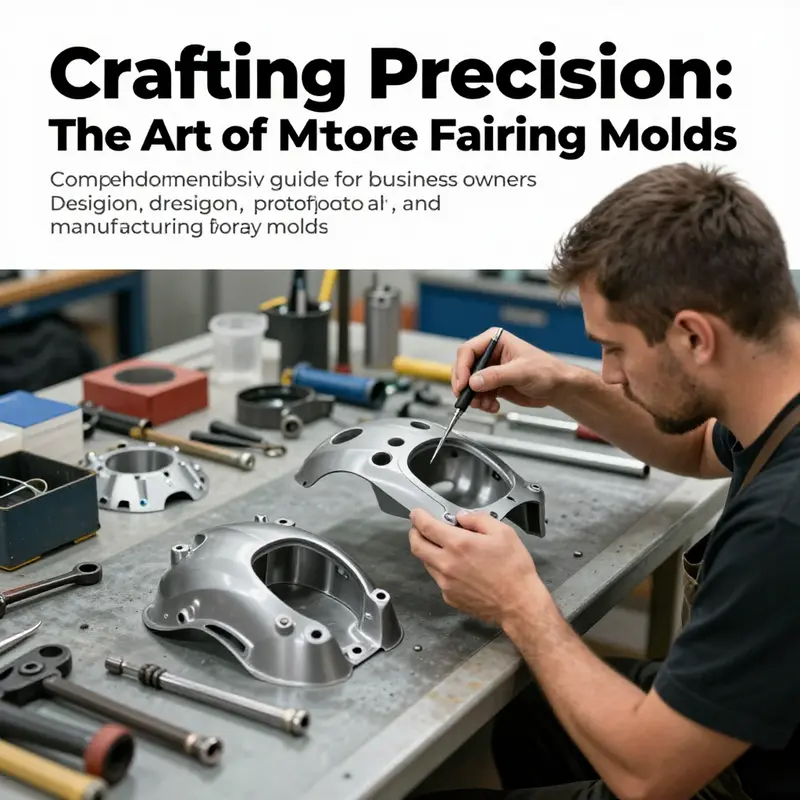
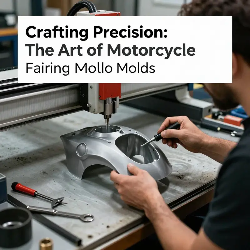
Once the CAD is finalized, produce a full-scale master or prototype that validates the digital intent. For fairings, many builders favor CNC-machined foam as a base because it combines dimensional accuracy with easy hand-finishing. Machine a block of rigid foam to the external shape, then refine it by hand to achieve the exact surface quality required for the mold. Alternatively, large-format 3D printing can create complex shapes quickly, but pay close attention to layer orientation and post-processing to remove stair-stepping. Regardless of the method, verify that the prototype matches the CAD model within a tight tolerance. Any deviation at this stage will be transferred into the mold and then into every part produced. For low-volume or concept runs, consider finishing the master with a thin gelcoat or primer fill to simulate the surface the composite or metal mold will see; this helps prevent surprises once tooling begins.
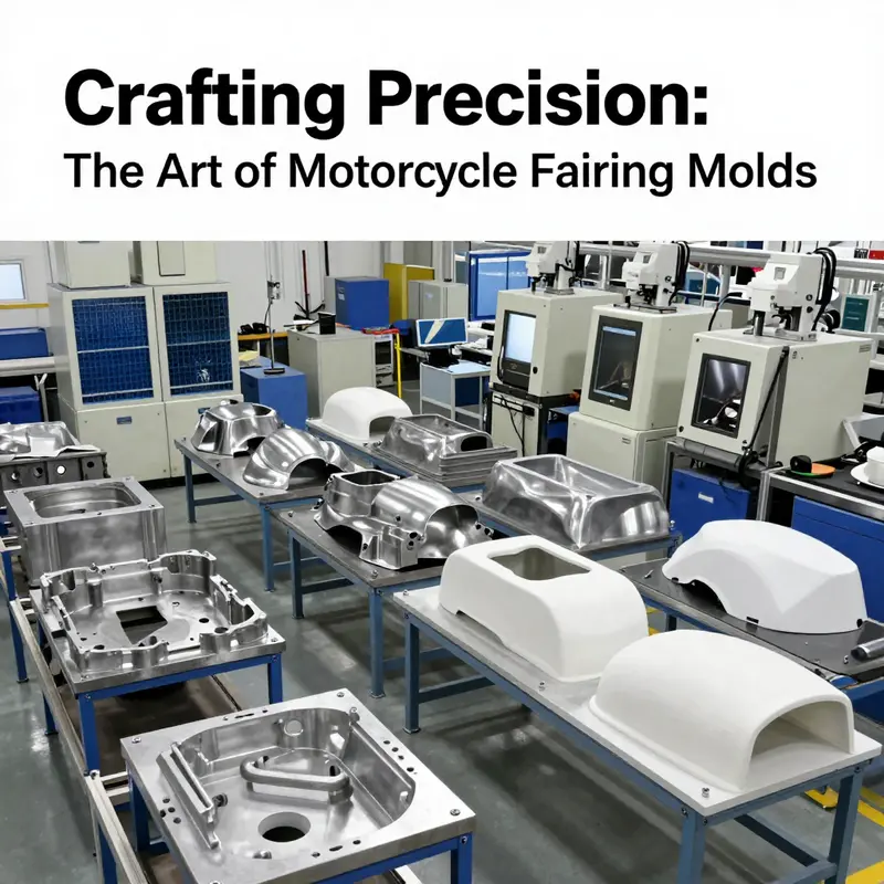
Selecting the mold material is a critical economic decision tied to expected production volume and part complexity. Composite molds made from fiberglass and epoxy resin are cost-effective and quick to produce, making them ideal for prototyping and small batch runs. They reproduce detail well and are straightforward to repair, but they wear faster and are sensitive to thermal cycling. For medium-volume production where hundreds or low thousands of parts are expected, aluminum molds strike a balance. Aluminum alloys such as P20 alternatives or medium-grade aluminum provide good machinability and thermal conductivity. They allow more aggressive cooling strategies, shorter cycle times, and longer life than composites. For very large volumes or parts with aggressive tolerances, hardened tool steels are the standard. Steel offers exceptional durability and can be polished to a mirror finish that endures, but the initial cost and machining time are substantially higher. Match the mold material to the commercial plan for the fairing: commit to steel only when volumes justify it.
The internal design of the mold—the core and cavity—must mirror the part in reverse while also accommodating process features. Design cavities to avoid undercuts that complicate ejection. When undercuts are unavoidable due to clip features or complex geometries, plan for slide mechanisms or collapsible cores. Integrate ejector systems early: pins are the simplest and most common solution, but for aesthetic panels that cannot tolerate pin marks, consider stripper plates, air ejection, or sleeve-type ejectors that localize the impact. Place ejector pins in non-visible areas such as inner mounting flanges whenever possible. Also account for thermal movement; the mold will expand and contract during cycles, so incorporate tolerances and clearances into the mechanical design to avoid binding or score marks.
Thermal management is where mold design transitions from static geometry to dynamic performance. Cooling channels must be designed to yield uniform temperature distribution across the cavity. Uneven cooling causes warpage, sink marks, and dimensional inconsistency. Use conformal cooling where feasible; channels that follow the contour of the cavity surface significantly improve thermal uniformity and shorten cycle times. When conformal cooling is not an option, optimize straight-drilled channels for proximity to critical wall sections and use simulation to identify hot spots. Circulate coolant at the right flow rate and monitor inlet and outlet temperatures across cycles. A consistent thermal baseline shortens the time needed for parts to reach final dimensions and reduces scrap.
The gate and runner system are the fluidic arteries of the mold. Their design determines how molten plastic fills the cavity and how the flow front behaves. For exterior fairings, surface appearance is paramount. Place gates in discreet locations like the flange area, under an overhang, or within a hidden recess. Use hot runner systems to eliminate cold runners and reduce waste when budgets allow. Hot runners keep the polymer in a molten state up to the gate, providing cleaner gates and faster turnaround between cycles. If a hot runner is not practical, design a runner layout that minimizes shear and maintains balanced flow to multi-cavity molds. Keep runner lengths short and use generous radii to avoid flow hesitation.
Venting is often overlooked but is essential. As molten plastic advances, it compresses and displaces air. Without proper vents, trapped air creates burn marks, short shots, or voids. Place vents along the end-of-fill flow paths and at the highest points of the cavity where air collects. Vents should be shallow and finely controlled to prevent flash while allowing air to escape. For highly detailed exterior panels, fine mesh venting or edge vents that are later trimmed can preserve surface quality.
Mold filling behavior should be validated using simulation tools. Mold-flow analysis reveals fill patterns, weld lines, air traps, and predicted shrinkage. Use these insights to adjust gate location, wall thicknesses, and cooling design before machining begins. Simulations help reduce iterative tool corrections by forecasting how the polymer will behave under real processing conditions. They are especially valuable when working with anisotropic materials, multi-gate arrangements, or complex internal rib structures.
When the tool is built, finishing touches define the aesthetic and functional quality of parts. Polish the cavity to the required finish level. A mirror polish produces glossy panels right out of the mold but increases tooling time. A satin finish can hide minor imperfections while still delivering great looks. Surface texturing can be used to mask mold marks and improve paint adhesion. Apply any necessary surface treatments or coatings that improve wear or release properties.
Testing and refinement are iterative. Perform initial test shots and inspect for flash, sink marks, dimensional variation, and warpage. Measure critical dimensions against the original CAD model and check mating surfaces for fit. If defects appear, analyze whether they stem from gating, cooling imbalance, ejection timing, or material selection. Small changes—adjusting gate size, adding or relocating vents, or modifying cooling flow—can dramatically improve outcomes. Maintain a log of each modification and its effect. That history is invaluable for troubleshooting and for future mold builds of similar parts.
Choosing the right resin is as important as the mold itself. Common choices for fairings include ABS blends, polycarbonate, and polypropylene, each with different strengths. ABS offers good impact resistance and paintability. Polycarbonate delivers superior strength and heat resistance but is more expensive and requires precise thermal control. Polypropylene is lightweight and chemically resistant but may be harder to paint without surface treatment. Select a resin based on desired stiffness, UV stability, impact behavior, and finishing requirements. Factor in how the chosen material shrinks so you can compensate in the mold design and machining tolerances.
Tolerances for mating surfaces and mounting points must be tight. Aim for dimensional control on critical features within ±0.1 mm when possible. This level of precision ensures panels fit subassemblies and fasteners without shims or rework. For complex assemblies, plan for a probing or in-line measurement system in production to catch drift early. Process control charts, temperature logs, and periodic dimensional checks keep production within specification.
Release strategy keeps cycle times predictable and parts unmarred. Apply appropriate release agents or use mold surface treatments that reduce sticking. In an industrial environment, automated spraying systems combined with wipe cycles can maintain coating consistency. For prototype composite molds, choose release waxes and agents that are compatible with both the mold and the chosen resin. Excessive release agent can interfere with paint adhesion, so strike a balance between part ejection reliability and finishing needs.
Finally, plan the mold lifecycle. Even the best-built tool will need maintenance. Schedule routine inspections for wear, check cooling channel integrity, and monitor surface quality. For aluminum and steel tools, re-polishing and re-machining small areas can extend usable life dramatically. Maintain a spare parts inventory of ejector pins, seals, and hot-runner components to minimize downtime.
For further technical depth on modern optimization of injection tooling for exterior components, consult the engineering literature on tool design and simulation-driven optimization such as the comprehensive study available at ScienceDirect: https://www.sciencedirect.com/science/article/pii/S0141635922001785
For practical examples of finished fairings and to reference shapes commonly produced in the industry, see categories of production panels like the selection of YZF fairings available at this resource: https://ultimatemotorx.net/product-category/yamaha-fairings/fairings-for-yzf/
This continuous, integrated approach—starting with a precise CAD model, validating via prototype, selecting the appropriate mold material, designing the thermal and gating systems carefully, and iterating through measured tests—produces molds that yield consistent, high-quality motorcycle fairings. Each decision informs the next, and careful documentation of choices and outcomes reduces iteration time on future projects. Treat the mold as a living asset: design for manufacturability, maintain it proactively, and refine it methodically to keep parts within spec and on schedule.
Prototype to Production: How Accurate Prototyping Shapes Motorcycle Fairing Molds
Prototyping is the crossroad where design intent, aerodynamics, and manufacturability meet. For motorcycle fairings, it is the stage that prevents expensive tooling mistakes, confirms fit and finish, and validates performance before committing to metal or composite molds. This chapter follows the prototyping journey from digital model to validated master, explaining methods, tolerances, iteration strategies, and how a well-run prototype phase shortens time-to-market while improving final mold quality.
The process always starts with a high-fidelity digital model. Engineers refine surfaces, define draft angles, and set parting lines in CAD. That virtual work must be translated into a physical master that represents the final fairing exactly. Any deviation in the master becomes a permanent error in the mold. Therefore, prototyping prioritizes dimensional accuracy, surface quality, and structural clues such as mounting points and reinforcement ribs.
Two broad prototyping approaches dominate the industry: high-precision CNC machining of foam or solid blocks and additive rapid prototyping using engineering-grade resins. Both have strengths. CNC machining produces a rigid, easily finished surface that mimics production material for fit checks. Additive methods excel at capturing complex internal geometries and accelerating iteration through quick turnaround. In many workshops these methods combine: an initial 3D-printed model for quick validation, then a CNC-refined master for final surface preparation.
A useful rule of thumb during prototyping is to treat the prototype as if it will become the final mold. That means applying the same surface tolerances, panel gaps, and attachment details you expect in production. Tight tolerances—often within ±0.1 mm on critical features—are enforced on mounting bosses and mating surfaces. Cosmetic areas, like large exterior panels and aerodynamic lips, require a mirror-smooth finish so paint and clearcoat will adhere and reflect correctly. When the prototype is not finished to that level, small imperfections will be amplified in the final mold and the resulting parts.
Surface preparation is where minutes in the workshop save weeks and thousands of dollars later. For CNC-machined prototypes, operators begin with a machined foam or light-density block that approximates the digital surface. Skilled hand-finishing follows: layering high-density filler sherpa or surfacing compound, sanding through progressive grits, and finally polishing to a near-mirror surface. For printed prototypes, sanding and post-cure processes are essential. Some printed resins accept thin urethane filler primers that can be sanded to remove layer lines. The goal is a continuous surface free of ripples, tool marks, or local irregularities that would transfer to the mold.
Beyond surface, prototyping validates mechanical interfaces. Fairings must secure to the frame, brackets, lights, and other components without stress. A prototype allows engineers to test bolt patterns, insert threads, and captive fasteners in real assemblies. During trial assembly, measure gaps around headlights, tank interfaces, and seat unions. Check that mounting bosses resist load and do not create stress risers when tightened. If a prototype reveals interference or deformation, designers can update CAD and iterate quickly, avoiding rework in the final tool.
Aerodynamics and airflow testing are central for performance-oriented fairings. A prototype that replicates real-world contours enables basic flow visualization tests and pressure tap measurements. Teams can fit pressure sensors or smoke visualization rigs to observe turbulence and wake behavior. Even without a full wind tunnel, on-bike track testing with the prototype fitted gives critical feedback about buffeting, cooling air direction, and rider comfort. If cooling ducts are mis-sized or the airflow path interferes with electronics, the prototype stage uncovers it early.
Another essential role of prototyping is to anticipate manufacturability constraints of the chosen mold material. A prototype will reveal areas that complicate mold release, undercuts that require side-actions, or extremely thin ribs that cause flow hesitation during injection. For composite molds, heat and cure behavior must be considered. Prototypes can be used to simulate thermal distortion or to test release agents and coatings that will be used in production. By catching these issues at prototype stage, toolmakers can design cooling channels, ejector systems, and venting into the final mold design wisely.
Materials chosen for prototypes influence testing fidelity. Engineering-grade resins deliver mechanical properties closer to final thermoplastics and can be used for short-run vacuum-formed parts or thermoforming trials. Rigid printed parts prove geometry; flexible resins can simulate thin-walled sections prone to deformation. Foam models, when coated and finished properly, are excellent for sanding and shaping and for large-format cosmetic checks. Many manufacturers in major hubs blend methods: rapid printed iterations for geometry validation, then CNC-machined masters for the final mold pattern.
Iteration is the heartbeat of prototyping. One prototype is rarely enough. Plan for successive builds, each targeting a narrower set of attributes: initial fit and form; then aerodynamic adjustments; then surface finish and attachment validation. Each pass should be measured and recorded with metrology tools. Coordinate measuring machines (CMMs) or portable scanners map deviations against the CAD baseline. A formal inspection report following each prototype iteration documents dimensional drift and improvement, so changes are intentional and traceable.
Time and cost are often the governing constraints. Many manufacturers outsource prototyping to specialist workshops that offer accelerated CNC and additive capabilities. In regions with integrated supply chains, prototype development can be closely linked to downstream painting and coating lines, shortening the feedback loop. When prototyping is coordinated with finishing vendors—paint shops, UV-coating specialists—surface treatments can be trialed directly on prototypes. This reveals how different coats affect appearance, adhesion, and UV stability before the mold is cut.
A practical but sometimes overlooked aspect is tooling shrinkage and material behavior. Thermoplastics shrink as they cool; composites can change dimension during cure. Prototypes allow engineers to observe these effects at scale. When making a prototype intended as a pattern for an aluminum or steel mold, allowances for shrinkage and thermal expansion must be included in the final tool design. Use prototype data to calibrate mold offsets and cavity dimensions so that production parts conform to the desired final dimensions.
Venting and part release are often discovered late in the process unless prototypes are used to simulate injection conditions. Small vents on prototypes help reveal where trapped air will cause burn marks or voids. Temporary venting features or sacrificial channels can be included in prototyped parts to test flow paths. Similarly, prototypes can be used to evaluate release agents and surface coatings, ensuring that parts separate cleanly from molds without damaging delicate finishes.
Prototyping also supports cost decisions. Composite molds are faster and cheaper to produce but wear faster under production. Metal molds cost more but survive higher shot counts. By building prototypes and running limited production tests, teams can estimate cycle life and per-part cost more accurately. Prototype-run parts subjected to accelerated aging tests—UV exposure, thermal cycling, and solvent resistance—help predict long-term performance and inform material selection for both parts and molds.
Communication is smoother when stakeholders can physically touch a prototype. Designers, engineers, suppliers, and clients align more quickly around a tangible object. Color, surface texture, and perceived quality become part of the discussion. When prototypes are used in supplier negotiations, they demonstrate readiness and reduce ambiguity about expectations for the final mold. For business-to-business relationships, the ability to show a validated prototype often shortens approval timelines and increases buyer confidence.
When planning prototyping, include a checklist of critical elements to validate on each pass: dimensional tolerances on mounting points, surface finish targets, aerodynamic performance indicators, fastener integrity, cooling-air behavior, venting effectiveness, and finish adhesion. Attach metrology records and photographic evidence to each report. Use these artifacts to feed the final mold design so the toolmakers get a clear, data-driven specification.
Finally, leverage regional capabilities if you can. Manufacturing hubs with dense supplier networks can integrate rapid prototyping with finishing and coating services. When prototype development is co-located with painting lines and UV coating specialists, testing for long-term UV resistance and final appearance can occur early and frequently. That integration reduces time-to-market significantly and helps suppliers deliver higher quality molds faster.
Prototyping is not a single task but a disciplined sequence of validations. It bridges the gap between a CAD model and a production-ready tool. When it is treated as an engineering phase with clear metrics, repeatable processes, and proper record-keeping, it saves time and money. It also gives the final mold a better chance of delivering consistent, high-quality fairings that fit precisely, perform aerodynamically, and finish flawlessly. Use prototypes to stress-test assumptions, to reveal hidden problems, and to lock down geometry and process parameters before the expensive step of final mold fabrication.
For those seeking deeper insight into how supply chains and regional manufacturing ecosystems amplify prototyping advantages, consult an industry overview of specialized component hubs. This resource explains how integrated supplier networks, rapid finishing capabilities, and access to automated coating lines combine to shorten development cycles and reduce cost while improving prototype fidelity and production readiness: https://www.global-sourcing-insights.com/china-motorcycle-fairing-supply-chain
For an example of finished fairing categories that commonly follow this prototyping-to-mold flow, see this collection of fairing models for a popular sportbike range: https://ultimatemotorx.net/product-category/honda-fairings/fairings-for-cbr
From CAD to Cast: Crafting Durable Molds That Shape Motorcycle Fairings
Turning a digital dream into a real, ride-ready shell is a quiet kind of engineering magic. Designers imagine the flow of air, the way a panel will resist impact, and the way mounting points will align with the bike’s frame. Then they hand that vision to machinists and toolmakers who translate it into a hardened reality: a mold that can reproduce consistent, high-quality plastic fairings at scale. The path from first sketches to the factory floor is not a single leap but a carefully choreographed sequence of decisions, each feeding the next with precision, material science, and an eye for manufacturability. Although the stages are discrete in description, the process unfolds as a fluent, iterative narrative where software, foam, metal, and plastic converse across time and tolerances. The outcome is a mold that is more than a cavity in metal or resin; it is the interface between aerodynamic intent and industrial reality, a watchful guardian of fit, finish, and durability across thousands or even tens of thousands of parts. In this chapter the arc from concept to casting is explored as a continuous manufacture story, one that blends design accuracy with the stubborn physics of heat, pressure, and polymer behavior. The aim is not merely to produce a fairing but to produce a repeatable, scalable geometry that can accommodate a family of variants without sacrificing the precision that defines a rider’s experience. The chapter weaves together the core ideas of design, prototyping, moldmaking, finishing, and production, and it does so with an eye toward the practicalities that determine whether a concept becomes a reliable component of a motorcycle’s silhouette and performance. Readers will trace how each decision—draft angles, material choice, cooling strategy, or the geometry of the gate—reverberates through the final part’s appearance and the tooling’s lifecycle, and they will see why the discipline of mold making is as much about discipline as it is about creativity. For those who wish to explore related catalog options as a practical supplement to this narrative, a representative catalog of fairings can be browsed through the broader product category linked here: fairings category.
The journey begins with design, a stage where a fairing’s shape is not simply a surface but a complex, aerodynamically informed form that must also be manufacturable. Modern workflows begin with three-dimensional CAD models that capture the geometry with micrometer-level fidelity. Engineers scrutinize airflow lines, ensure structural reinforcements won’t impede forming, and anticipate how mounting points will interface with the motorcycle’s frame. The digital model must translate to a real part that preserves its curvature, line transitions, and subtle features under the inevitable realities of molding. Surface refinement becomes a central craft: the mesh must be cleaned, continuity must be established, and every transition between surfaces must be free of gaps or abrupt tangents that would telegraph flaws into the finished part. In practice this means leveraging advanced software to optimize surfaces, detecting tangency and curvature issues that could cause mold-separation difficulties or visible finish problems on the final part. Draft angles and parting lines—typically modest, 2 to 5 degrees, designed to promote reliable ejection—are laid out at this early stage. The choice of parting line locations is not a cosmetic concern; it determines how the mold halves will come apart and how the surface detail will be preserved across size and thickness variations. A good mold plan anticipates the entry path of the plastic as it fills the cavity and the way flash might form if the surfaces are misaligned or if the cooling is uneven. Detail here becomes destiny in the finished piece.
With a mature digital model in hand, the process moves into the creation of a master model—a tangible, often full-scale representation that the mold will replicate. The master serves as the physical bridge between the virtual and the real. A common approach is to machine a foam block with CNC, then refine the surface by hand to capture the exact textures and radii defined in the CAD model. Foam or wood masters can be faster to produce and easier to adjust, but they must be true to the digital design, because every surface imperfection will imprint onto the mold and, ultimately, onto every molded part. When the master is completed, a precise inspection protocol follows: a gauged comparison against the CAD reference, spot measurements at critical radii, and a careful check of silhouette features that affect aerodynamics. The accuracy of the master is non-negotiable; once the master is used to generate the mold, there is little room for large corrections without costly rework. In some high-end programs, artists may create a “high-poly” sculpt for visualization, then translate the design into a production-ready, lower-polygon geometry used to generate the final tooling. This step ensures that the aesthetic intent survives translation from the digital realm into the physical form, while keeping tolerances tight enough to ensure consistent replication across thousands of parts.
The mold itself is the heart of the operation, and material choice becomes a strategic decision that balances volume, surface quality, cycle time, and durability. Aluminum molds are favored for mid- to high-volume production because they offer good durability and fast heat transfer, which helps minimize cycle times across large runs. They are robust enough for complex geometries yet lighter and more forgiving to machine than steel. For extremely high-volume runs or where the geometric complexity or long tool life justifies it, steel molds come into play. They deliver exceptional wear resistance and longevity but at a higher initial cost and longer lead times for machining. Composite molds, such as fiberglass or resin-based tooling, provide an economical path for low-volume or prototyping runs. They can be built quickly and modified with relative ease, but they cannot withstand the same thermal cycling and long-term wear as metal molds. The master pattern yields the actual cavities through a process of precise machining, often creating a core and cavity arrangement that mirrors the desired exterior and interior surfaces of the fairing. The two-plate mold remains the archetype in many factories; it splits along a single parting line, opening to reveal a male core and a female cavity that mirror each other with incredible precision. Within the mold, cores, cavities, and inserts are laid out to reproduce the fairing’s exterior geometry while accommodating the undercuts, ribs, and stiffening features that a real panel would require for durability and shape retention.
Ejection systems and cooling channels are the unsung lifeblood of mold functionality. An efficient ejection arrangement, including pins and sleeves, guarantees that the part is removed without damage or distortion after cooling. The cooling network is not merely a convenience; it is a critical contributor to dimensional stability. The position, size, and pattern of cooling channels govern how evenly the material solidifies, how warpage is controlled, and how cycle times can be optimized. Inadequate cooling can lead to residual stresses that manifest as surface waviness or part-to-part dimensional drift, especially across large fairing panels. The interplay between mold temperature, resin selection, and part geometry requires careful calibration. Material choice—ABS, polycarbonate, or polypropylene, among others—dictates not only mechanical performance but also how heat is conducted away from the gate, how the melt fills, and how shrinkage behaves as the part cools. The gate location and the runner system influence flow balance, potential air entrapment, and the likelihood of surface defects such as weld lines or sink marks. Designers aim for a balanced fill that avoids abrupt transitions, which can become visible under a paint finish or functional as a stress concentrator in service.
The finishing and quality control phase transforms a technically sound mold into a reliable production tool. The mold surfaces require a mirror finish that minimizes the introduction of texture in the final plastic parts, unless a specific texture is part of the design language. Polishing the mold is a craftsmanship activity as much as a machining task; it demands an understanding of how polishing grooves will affect final gloss, how minor scratches will reveal under pigment, and how to maintain consistent surface quality across all cavities. Once a test shot is run, the parts are scrutinized for flash, which is the thin excess material at the seam, sink marks that betray cooling inefficiencies, warpage resulting from uneven shrinkage, and any dimensional inaccuracies that could interfere with mounting points or adjacent panels. If a problem is detected, adjustments are logged, and the mold may be shimmed, polished a little deeper, or an insert repositioned to correct the mismatch. The release agents, applied before each cycle, play a crucial role in preventing sticking and facilitating clean ejection. These agents must be compatible with the chosen resin and the mold surface chemistry to avoid residue that would affect paint adhesion or surface feel in the final part. The cycle of testing, adjusting, and re-testing becomes a disciplined loop, iterating until the shot parts consistently meet the design tolerances and aesthetic expectations.
Documentation and tolerances form the quiet backbone of repeatable production. Dimensional tolerances for automotive and motorcycle components are tight, often within tenths of a millimeter. Even small deviations can cascade into misalignment with other panels, gap inconsistencies along edges, or misfit of fasteners. A common target is ±0.1 mm or better for critical surfaces, with more generous allowances in non-critical regions. This is not a capricious standard; it emerges from the need to assemble a bike with panels that click into place without adjustment, maintain a seamless appearance under paint, and withstand the rigors of vibration and thermal cycling on the road. Venting is another practical concern. Small vents allow air to escape from between the mold halves as the mold closes, preventing air pockets that could lead to voids, and they are carefully sized to avoid leakage of molten resin. A well-designed vent system also helps avoid burn marks and splay on the surface, preserving the pristine exterior condition that riders demand.
As the mold proves itself on test shots, it becomes more than a passive cavity; it turns into a reliable partner in production. The transition to serial manufacturing marks a shift from design and refinement to process control. Injection molding requires meticulously tuned process parameters: melt temperature, injection speed, holding pressure, and cooling time all converge to determine part quality and cycle efficiency. The resin selected—its stiffness, impact resistance, UV stability, and color retention—dictates the handling and performance of the final panel. Ultra-high demands for color consistency drive careful control of resin batches, flow characteristics, and melt rheology. The mold is calibrated for these conditions, and the machine parameters are adjusted to minimize variability from cycle to cycle, from shot to shot, and from part to part. Yet even the best-controlled processes must accommodate occasional variability in raw materials or ambient conditions. A robust mold sustains this variability by maintaining dimensional stability and offering consistent surface finish across a production run.
The lifecycle of a fairing mold does not end with a single program. The industry understands that mold wear, material evolution, and changing aesthetic requirements can necessitate rework or even replacement after long service. In many facilities, the mold is re-worked by re-machining corners, re-polishing a high-wear surface, or adding protective inserts to extend its life. When a new fairing family is introduced—whether to accommodate a new model variant or to refresh the visual language—the process often begins anew, looping back to digital design, master modeling, and mold qualification to ensure that the new form can be produced with the same confidence as the existing catalog. Within that loop, the role of standards and guidelines becomes explicit. The design, manufacturing, and inspection practices align with industry standards and guidelines, such as recognized materials and process guidelines, to ensure that the mold not only performs today but is also capable of supporting future projects. This confluence of design rigor, manufacturing discipline, and constant iteration is what makes the seemingly simple plastic shell a reliable, high-performance component of a motorcycle’s form and function.
In practice, the overall success of fairing molding hinges on the quality of the initial digital design and the fidelity of the master model. The design team must anticipate how the final part will be handled in paint booths and assembly lines, how the surface texture will interact with coatings, and how mounting interfaces will align with other components across a range of models. The toolmakers translate this plan into a physical, highly engineered tool that can sustain thousands of cycles without sacrificing accuracy. The production engineers then implement a robust process window—one that tolerates minor fluctuations yet guarantees uniform results. The synergy of CAD accuracy, master fidelity, material selection, precise machining, controlled cooling, and careful finishing becomes a single, repeatable workflow. The result is a family of durable, aesthetically consistent fairings that perform as well on the road as they look in the showroom. The mold is the quiet constant behind that performance, a technical artifact whose value is measured not just in the number of parts produced but in the confidence it gives designers, manufacturers, and riders alike.
For readers who want to explore the broader context of this domain, a practical reference can be found in industry-level materials that discuss how the molding process intersects with standards, testing, and best practices. The reference below offers a deeper dive into the manufacturing process, including the considerations described here and additional techniques used in modern production environments. External resource: https://www.motorcyclefairing.com/manufacturing-process/
Internal resource for exploration of fairing options: fairings category. The catalog link provides a sense of how different surface aesthetics and structural reinforcements translate into separate tooling challenges, reminding readers that even visually similar panels may require distinct mold strategies. While brand mentions appear in the catalog structure, the emphasis here remains on the moldmaking logic that governs the production of any fairing, regardless of the chosen aesthetic language. This alignment between design intent and tooling capability helps bridge the gap between the art of shaping a motorcycle’s silhouette and the science of delivering it reliably at volume.
Final thoughts
Understanding the intricacies of creating motorcycle fairing molds is essential for business owners aiming to enhance their competitive edge. From skilled design to precise prototyping and proficient mold creation, each step plays a pivotal role in producing high-quality, reliable motorcycle fairings. Investing time and resources in mastering these processes not only improves product quality but can also lead to greater operational efficiencies and increased market responsiveness. Therefore, as you implement these strategies, remember that excellence in mold-making can significantly define the success of your motorcycle components business.